
The K type thermocouple is one of the most widely used industrial temperature sensors in flexible heaters due to its broad measurement range, durability, fast response, and relatively low cost. Whether you are working in plastics processing, industrial heating, metallurgy, HVAC, scientific instrumentation, or electronics manufacturing, Type K is often the first thermocouple you consider.
This article explains everything you need to know about Type K thermocouples, including their materials, color codes, how to read a K type thermocouple chart, common failure modes, differences versus Type J, polarity rules, and how to properly test one.
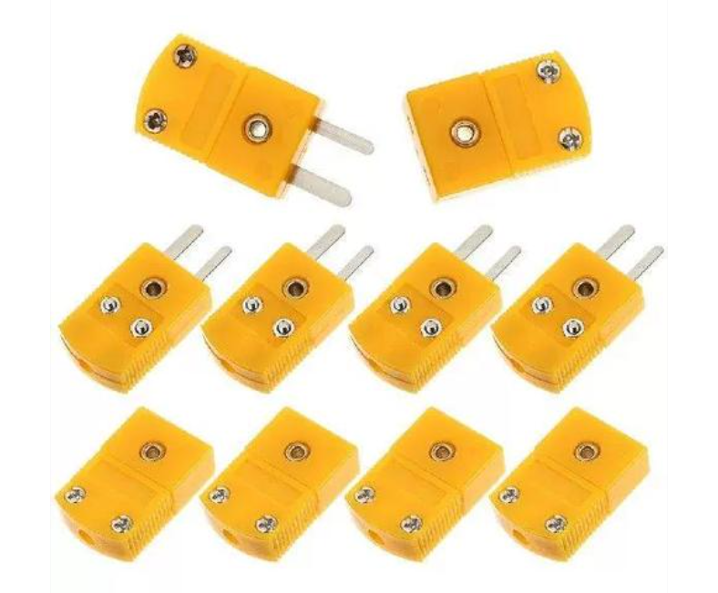
A K type thermocouple is a temperature measurement device made from two dissimilar metal wires: Chromel (positive) and Alumel (negative). When the two metals are joined at one end and exposed to temperature, they generate a small voltage based on the Seebeck effect. The voltage increases in a predictable way as temperature rises.
Key advantages
This combination makes the Type K the industry standard for furnaces, industrial heaters, plastic molding machinery, food processing, lab experiments, gas turbines, engines, and more.
A Type K thermocouple is made from two specific alloys, chosen for their repeatable thermoelectric properties at high temperatures.
1. Chromel (Positive Wire)
2. Alumel (Negative Wire)
These alloys work well together because their combined temperature-voltage curve is highly repeatable. Chromel handles air exposure at elevated temperatures better than many alloys, while Alumel offers a smooth counter-response that forms a stable voltage relationship.
The pairing helps the K type achieve a good balance of performance, affordability, and durability in heater systems. These materials also function effectively in oxidizing environments—a major reason Type K is more common than Type J in high-temperature settings where oxidation could damage the junction.
Identifying a thermocouple’s polarity is essential for proper installation. The k type thermocouple color code follows international wiring standards that help engineers avoid polarity mistakes.
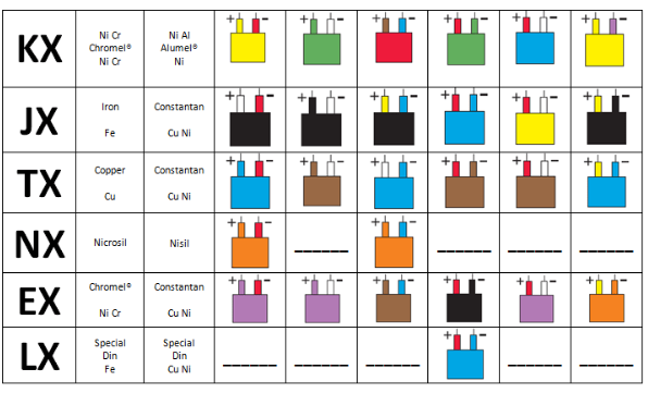
| Function | Wire Material | Color (USA ANSI) | Color (IEC) |
| Positive Lead | Chromel | Yellow | Green |
| Negative Lead | Alumel | Red | White |
| Outer Jacket | — | Yellow | Green |
The positive wire always corresponds to Chromel, and the negative wire corresponds to Alumel. The yellow outer sheath (ANSI) or green outer sheath (IEC) helps engineers identify the cable type even when the individual conductors are not visible.
A k type thermocouple chart is a reference table that shows the relationship between the sensor’s millivolt output and actual temperature. Engineers use these charts during calibration, testing, and troubleshooting.
Reading the chart is simple:
A K type thermocouple generates roughly 1 mV every 25°C. At 100°C, the output is typically around 4.095 mV (exact values depend on the chart). Chart reading is useful when verifying whether a heater system produces correct values during development or troubleshooting.
Typical Output Example (Reference)
| Temperature (°C) | Millivolt Output (mV) |
| 0°C | 0.000 mV |
| 100°C | 4.095 mV |
| 300°C | 12.209 mV |
| 600°C | 25.397 mV |
| 1000°C | 41.276 mV |
These values highlight the steady voltage progression that engineers rely on when building closed-loop heater systems.
Even though Type K thermocouples are durable, they are still vulnerable to several failure modes.
1. Oxidation at High Temperature
Chromel and Alumel oxidize when continuously exposed to temperatures above 1000°C.
Oxidation thins the wire and changes its composition, causing output drift.
2. Contamination
Exposure to sulfur, chlorine, or reducing atmospheres causes chemical reactions that damage the metal wires. This leads to unstable, inaccurate readings.
3. Thermal Shock and Cycling
Rapid heating and cooling can cause the junction to crack or drift.
4. Electrical Noise
High-power heaters, motors, and switching devices introduce EMI, which causes unstable voltage readings.
5. Mechanical Damage
Crushed cables, vibration, bent probes, and wear at the junction cause opens or shorts.
6. Ground Loop Issues
If the thermocouple junction is grounded while the instrument expects an ungrounded probe, measurement noise or offset errors occur.
7. Incorrect Installation
Improper insulation, touching metal sheaths, or incorrect polarity causes unreliable readings.
Type J and Type K thermocouples share similar principles, yet they differ in alloy composition, usable temperature range, and durability.
| Feature | Type K | Type J |
| Positive Material | Chromel | Iron |
| Negative Material | Alumel | Constantan |
| Temp Range | –200°C to +1260°C | –40°C to +750°C |
| Oxidation Resistance | Excellent | Poor above 550°C |
| Stability | Good | Good in reducing atmospheres |
| Cost | Moderate | Slightly lower |
| Best Use | General industrial use, heaters, furnaces | Older equipment, reducing atmospheres, heat-treated steels |
Summary
For most modern applications, Type K is preferred unless the equipment is designed specifically for Type J.
The positive wire on a Type K thermocouple is the Chromel leg.
Color codes:
The negative wire is the Alumel leg (red in ANSI, white in IEC).
In every case, incorrect polarity leads to backward voltage readings and incorrect temperature values.
Testing a K type thermocouple verifies whether its junction, wiring, and response behavior function correctly.
1. Visual Inspection
Check insulation, connectors, and the exposed junction for corrosion, cracks, or discoloration.
2. Confirm Polarity
Ensure Chromel (yellow) is positive and Alumel (red) is negative.
3. Measure Millivolt Output
Use a digital multimeter set to millivolts. Warm the junction gently and observe whether the reading increases smoothly.
4. Compare with a K Type Chart
Match the measured millivolts with the expected temperature. A large mismatch may indicate drift or damage.
5. Perform a Continuity Test
Use a multimeter’s continuity mode to check whether the circuit is intact.
6. Use a Temperature Source
Immerse the sensor in boiling water (~100°C) or an ice bath (~0°C) to verify calibration points.
If the output behaves inconsistently, or if values do not align with the chart, replacement may offer the best results.
1. What temperature range can a K type thermocouple measure?
It typically covers –200°C to 1250°C, depending on insulation and construction.
2. Why does my Type K thermocouple reading drift over time?
Drift usually occurs due to:
3. Can a Type K thermocouple be used in vacuum or reducing atmospheres?
Type K is not ideal for reducing or vacuum environments. In these atmospheres, the chromium in Chromel is reduced, causing rapid drift. For vacuum or reducing atmospheres, Types N, R, S, or T are better choices.
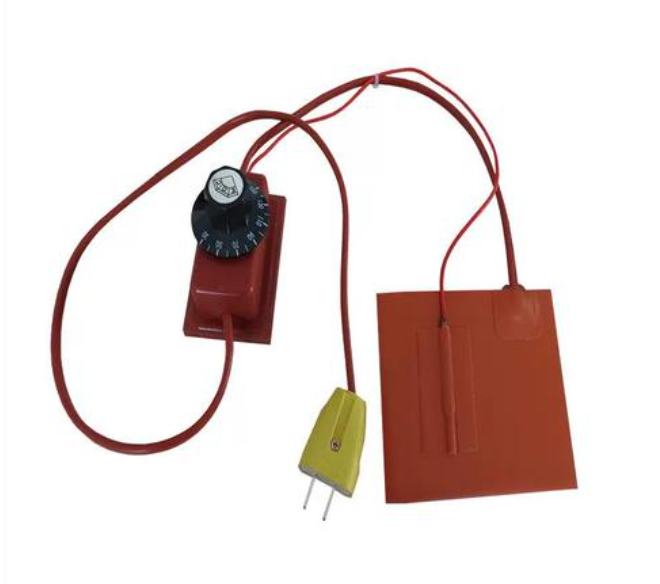
4. Can a K type thermocouple be used in flexible heaters?
Yes. It works smoothly with polyimide heaters, silicone rubber heaters, and transparent heaters.
5. Does Danyu Electronics offer custom thermocouple integration for heaters?
Yes. Danyu Electronics provides heater products with custom K type thermocouple placement, wire routing, bonding films, and connector solutions.
Danyu Electronics supports heater solutions built around reliable K type thermocouples, offering custom sensor placement, wire routing, bonding structures, and insulation options. With consistent engineering support and controlled manufacturing processes, your heater system can reach better repeatability, faster response, and long-term performance across different environments.
If your project requires precise thermal control or you need guidance integrating a K type thermocouple into your heater design, Danyu Electronics can provide technical input, fast sampling, and tailored manufacturing support.
+86 (755) 2909-1601
sales@best-heaters.com
5F, Bld7, Hengmingzhu Technology Industry Park, Xingqiao Tongfuyu Industry Zone, Gonghe, Shajing Town, Baoan District, Shenzhen,China
Simply drop your email or phone number in the contact form, and we'll promptly reply you shortly.